How does unmetered air bypass around an improperly seated air filter (1K0 129 620 D / 5C0 129 620) affect long-term fuel trim (LTFT) adaptations and VGT vane control on the Audi Q3 2.0 TDI Quattro?
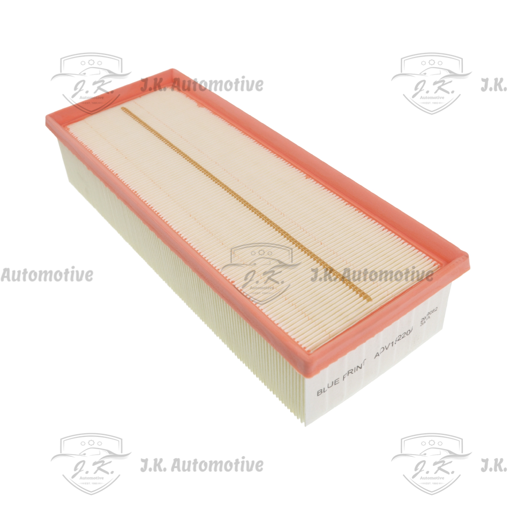
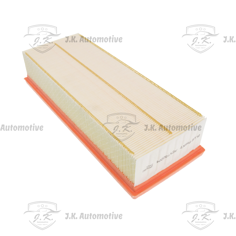
When an air filter element matching part number 1K0 129 620 D or 5C0 129 620 is installed improperly inside the PQ35 airbox housing—due to rolled gasket perimeter seals, pinched polyurethane edges, or misaligned lower housing locator tabs—unmetered "tramp" air enters the intake tract directly downstream of the filter frame. In the EA188 / EA288 2.0 TDI engine, this unmetered air creates severe telemetry discrepancies across the hot-film Mass Air Flow (MAF) sensor grid and downstream Manifold Absolute Pressure (MAP) sensors. Because the Bosch EDC engine control unit relies on precise physical air mass measurements to calculate target diesel fuel injection pulse widths and electro-hydraulic Haldex torque limits, unmetered air causes actual cylinder air charge to exceed measured air mass. The ECU's closed-loop lambda control detects an lean air-fuel mixture via the wideband oxygen sensor, driving Long-Term Fuel Trim (LTFT) adaptations into positive offset corrections as the system injects additional diesel fuel to achieve targeted stoichiometry. Concurrently, the ECU detects an anomaly between calculated volumetric efficiency and actual intake manifold pressure, prompting the electronic N75 solenoid to manipulate variable-geometry turbocharger (VGT) actuator duty cycles erratically. The turbine vanes cycle open and closed rapidly in an attempt to stabilize boost pressure, leading to hunting boost levels, elevated exhaust gas temperatures (EGTs), accelerated mechanical wear on the VGT guide-vane mechanism, and premature carbon fouling of the variable turbine nozzle ring. Hygroscopic Salt Evaporation & Pore Crystallization: As damp air passes through the filter media during sustained driving, ambient engine bay heat evaporates the liquid water component of the ingested spray. However, dissolved sodium chloride ($text{NaCl}$) and calcium chloride ($text{CaCl}_2$) road salts cannot evaporate. The salt molecules precipitate out of solution, forming microscopic crystalline salt structures deep inside the 3-micron fiber pores. Over repeated wetting and drying cycles, these salt crystals expand, locking onto the synthetic fibers and blinding the media matrix from the inside out.
What physical design differences exist between cold-climate pre-fleece air filters (1K0 129 620 G / 1KD 129 620 B) and standard synthetic elements, and how do they function under severe winter spray conditions on the Audi Q3 2.0 TDI?
Certain OEM air filter cross-reference part numbers for the Audi Q3 (8UB, 8UG) 2.0 TDI—specifically 1K0 129 620 G and 1KD 129 620 B—feature an auxiliary white synthetic pre-filter fleece wrap laminated directly onto the raw pleat intake face. This dual-stage design is engineered by VAG thermal and filtration engineers specifically for severe cold-climate geographic regions and winter driving conditions where road salt spray, heavy slush, and fine airborne snow crystals enter the front radiator grille cold-air ducting. Standard single-stage synthetic microfiber elements without pre-fleece wraps risk absorbing liquid moisture when driven behind winter salt-spreading vehicles; as salt-laden slush hits warm media inside the airbox, moisture evaporates, leaving concentrated salt crystals that recrystallize deep within the 3-micron media pores, blinding the filter face and causing rapid intake vacuum spikes. The specialized pre-filter fleece acts as a hydrophobic barrier and surface-depth depth-loading filter: it traps slush, large salt spray droplets, and coarse road debris on its outer permeable surface before they reach the main pleated microfiber matrix underneath. This enables the primary pleat valleys to remain completely dry and open for clean airflow, preserving volumetric efficiency, preventing filter freeze-over during sub-zero overnight parking, and maintaining baseline pressure differentials across the intake tract even during extended winter highway driving. Droplet Repulsion & Surface Runoff: Under initial exposure to liquid road spray, the hydrophobic coating prevents water molecules from wetting individual micro-fibers. Water droplets bead on the outer pleat tips and roll down into the lower airbox basin, where they are discharged through the spring-loaded lower drain flutter valve.
How does a degraded or distorted air filter (1K0 129 620 D / 5C0 129 620) alter mass airflow sensor signal frequency and hot-film cooling telemetry in the Audi Q3 2.0 TDI Quattro?
The hot-film Mass Air Flow (MAF) sensor mounted immediately downstream of the airbox housing in the Audi Q3 2.0 TDI relies on a delicate heated platinum film element kept at a constant temperature differential relative to incoming ambient air. As intake air flows across the sensor grid, it cools the platinum film, requiring the sensor’s internal circuit to vary electrical current to maintain that fixed temperature delta; this current change is converted into an ultra-precise voltage signal representing exact intake air mass. When an air filter element matching part number 1K0 129 620 D or 5C0 129 620 suffers from warped pleats, damaged media, or missing hot-melt stabilization lines, the incoming airflow profile degenerates from a smooth, laminar stream into a highly turbulent column filled with localized pressure spikes and chaotic micro-eddies. This uneven air distribution causes localized thermal shock and erratic cooling across the platinum hot-film element, producing high-frequency electrical signal noise ("signal jitter") in the MAF sensor output. The Bosch EDC ECU interprets these rapid voltage oscillations as instantaneous, physically impossible fluctuations in engine air intake. To prevent severe engine knock or overboost conditions, the ECU retards common-rail diesel injection timing and modulates the variable-geometry turbocharger (VGT) vane position erratically. Over time, micro-particulates bypassing a compromised filter coat the platinum element in a fine insulating layer of grime, causing "thermal lag"—where the sensor under-reports actual air mass during rapid acceleration—resulting in sluggish throttle response, heavy smoke creation, and diagnostic trouble code P0101 (MAF Sensor Circuit Range/Performance Implausibility). For vehicles operated in harsh winter regions with heavy road salting, visual inspection of filter 1K0 129 620 D / 5C0 129 620 every 15,000 kilometers is mandatory, with complete element replacement recommended immediately following the winter season to remove salt-bound media and preserve full intake volumetric efficiency.
How do extreme ambient humidity, heavy rain ingress, and standing water splash impact the hydro-phobic properties of OEM filter 1K0 129 620 D / 5C0 129 620, and what prevents hydro-lock in the Audi Q3 2.0 TDI Quattro?
Driving the Audi Q3 2.0 TDI Quattro through heavy torrential rainstorms, standing highway puddles, or deep water crossings subjects the front cold-air intake ducting—located directly behind the upper front grille—to severe liquid water ingression. Genuine OEM air filter part numbers 1K0 129 620 D and 5C0 129 620 incorporate advanced hydrophobic chemical binders within their synthetic microfiber matrices designed specifically to repel liquid water droplets while permitting gaseous air molecules to pass freely. When high-speed road spray enters the lower airbox housing, the hydrophobic treatment causes water droplets to bead up on the outer pleat face and roll downward into the bottom of the airbox tray rather than soaking into the media fibers. This water management system relies on two critical design features: the primary hydrophobic media barrier and the lower airbox housing’s spring-loaded rubber drain valve. If the rubber drain valve is clogged with mud or leaf debris, standing water accumulates inside the lower tray; under heavy acceleration, the turbocharger's intense suction vacuum can pull pooled water against the filter face. If an unapproved non-hydrophobic paper filter is installed, the paper fibers absorb water, expand, lose structural integrity, and tear open under vacuum, allowing raw liquid water to be sucked straight through the compressor wheel and intercooler into the engine cylinders. Because diesel engines operate at extremely high static compression ratios (exceeding 16.0:1) with minimal combustion chamber clearance volume, ingesting even a few milliliters of liquid water causes catastrophic mechanical hydro-lock—instantly bending connecting rods, snapping gudgeon pins, and destroying the engine block. Hydrophobic Resin Breakdown: Chemical exposure to aggressive road-deicing agents combined with freezing temperatures degrades the synthetic hydrophobic resin coating over time. Once the coating breaks down, the microfiber pleats begin to absorb moisture directly into their structural matrix. Wet pleats swell, lose their bending stiffness, and collapse under intake suction vacuum, leading to immediate airflow restriction and engine power reduction.
How does progressive microscopic boundary-layer restriction on synthetic air filter 1K0 129 620 D / 5C0 129 620 dynamically alter compressor wheel aerodynamics, blade tip stall, and surge margin limits in the Audi Q3 2.0 TDI Quattro?
In the forced-induction architecture of the Audi Q3 (8UB, 8UG) 2.0 TDI Quattro, the intake air filter element (1K0 129 620 D / 5C0 129 620) acts as the primary fluidic boundary regulating pressure delta before incoming air enters the variable-geometry turbocharger compressor inlet neck. When the multi-layered synthetic microfiber pleats become progressively blinded by ultra-fine particulate matter, silica dust, and environmental soot, the fluid mechanics governing compressor operation shift dramatically. Under clean airbox conditions, the compressor wheel accelerates ambient air through a uniform laminar flow profile, maintaining an optimal angle of attack relative to the leading edge of the aluminum compressor blades. However, as static intake depression vacuum behind a restricted filter element exceeds baseline operating thresholds, fluid pressure drops rapidly while air velocity profile across the inlet neck degrades into erratic, turbulent micro-eddies. This severe inlet starvation creates localized boundary-layer separation across the suction face of the spinning compressor blades. As the pressure ratio across the turbocharger increases against an artificially high depression vacuum, the turbocharger operating point on its thermodynamic performance map shifts dangerously toward the left boundary—known as the compressor surge line. During sudden off-throttle decelerations or high-load transient shifts under Haldex Quattro engagement, the airflow velocity stalling across the compressor blade tips can momentary reverse direction. This instigates violent aerodynamic compressor surge, where high-pressure air downstream of the compressor discharge pulses backward across the spinning impeller. The resulting axial thrust reversals place catastrophic mechanical shock loads on the turbocharger’s internal floating journal bearings, 360-degree thrust bearings, and shaft seals. Over time, sustained boundary-layer separation leads to subtle compressor blade tip erosion, shaft deflection, unbalancing of the rotating assembly, and premature oil leakage into the charge air system. Maintaining an unrestricted, high-flow filter element 1K0 129 620 D / 5C0 129 620 ensures stable compressor inlet velocity profiles, preserves critical aerodynamic surge margins, and protects the high-speed rotating assembly under all engine load conditions.
How do micro-structural alterations in the pore matrix of filter 1K0 129 620 D / 5C0 129 620 influence hot-film Mass Air Flow (MAF) sensor calibration drift, fuel injection timing maps, and torque calculation vectors in the Bosch EDC system?
The electronic engine management platform (Bosch EDC17 / EDC16) governing the Audi Q3 2.0 TDI engine calculates fuel injection mass, pilot-main-post injection timing split, and torque output using complex mathematical model vectors driven primarily by telemetry from the hot-film Mass Air Flow (MAF) sensor. The MAF sensor relies on a uniform, predictable velocity profile across its measuring element to accurately quantify the physical mass of air entering the intake manifold per millisecond. When an air filter element (1K0 129 620 D / 5C0 129 620) experiences physical pleat distortion, structural breakdown, or localized pore clogging, the air stream exiting the clean side of the filter barrel loses its uniform velocity distribution. Instead of a smooth, flat velocity profile, the air stream forms localized high-velocity "jets" and low-velocity dead zones within the intake pipe. When a high-velocity jet passes directly over the MAF sensor’s heated platinum element, the sensor over-reports total air mass mass. Conversely, if a dead zone aligns with the sensor element, intake air mass is severely under-reported. This sensor telemetry corruption induces immediate mathematical anomalies within the ECU’s inner torque calculation loops: Under-Reported Airflow (Thermal Lag & Soot Generation): If the sensor under-reports actual air mass due to turbulent masking, the ECU restricts main fuel injection pulse widths to prevent perceived rich combustion. The driver experiences severe throttle lag, delayed boost buildup, and sluggish acceleration. If post-injection cycles are active for DPF regeneration, incorrect air mass calculations lead to improper exhaust gas temperatures, leaving unburned fuel in the cylinder. Over-Reported Airflow (Excessive Thermal Stress): If localized jetting causes the sensor to over-report air mass, the ECU commands aggressive diesel fuel injection quantities that exceed the physical oxygen mass available in the combustion chamber. This creates instantaneous local rich zones during the flame propagation phase, spiking peak cylinder temperatures, generating heavy black carbon soot, and driving cylinder pressure rise rates ($dP/dtheta$) beyond structural limits. Installing a genuine OEM specification filter element with hot-melt pleat stabilization beads locks the media pleats at precise structural intervals, ensuring that the velocity profile past the MAF sensor wire remains laminar and linear across the entire engine speed range.



Reviews
There are no reviews yet.